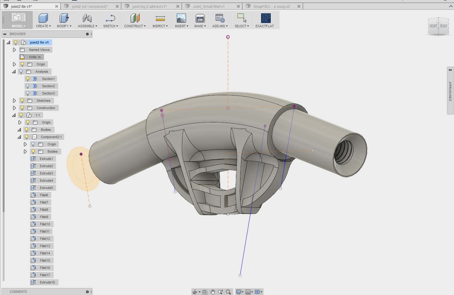
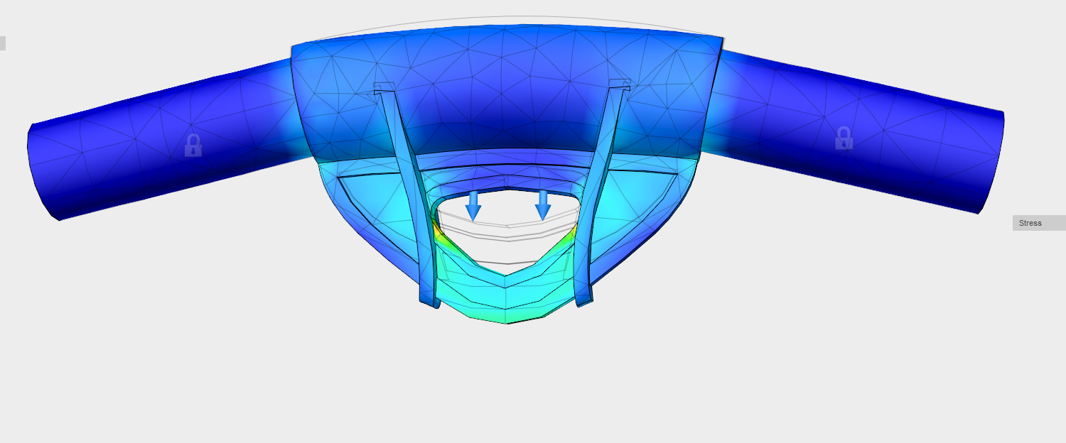
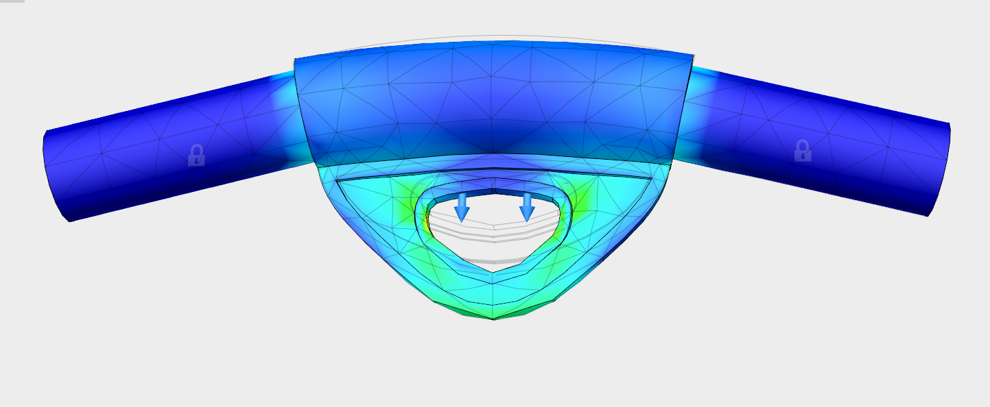
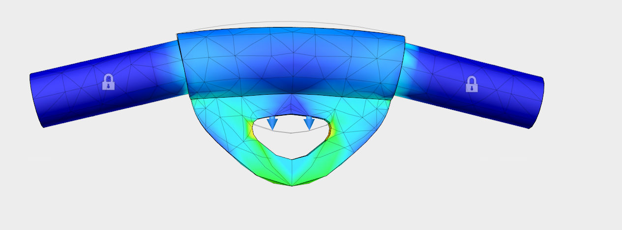
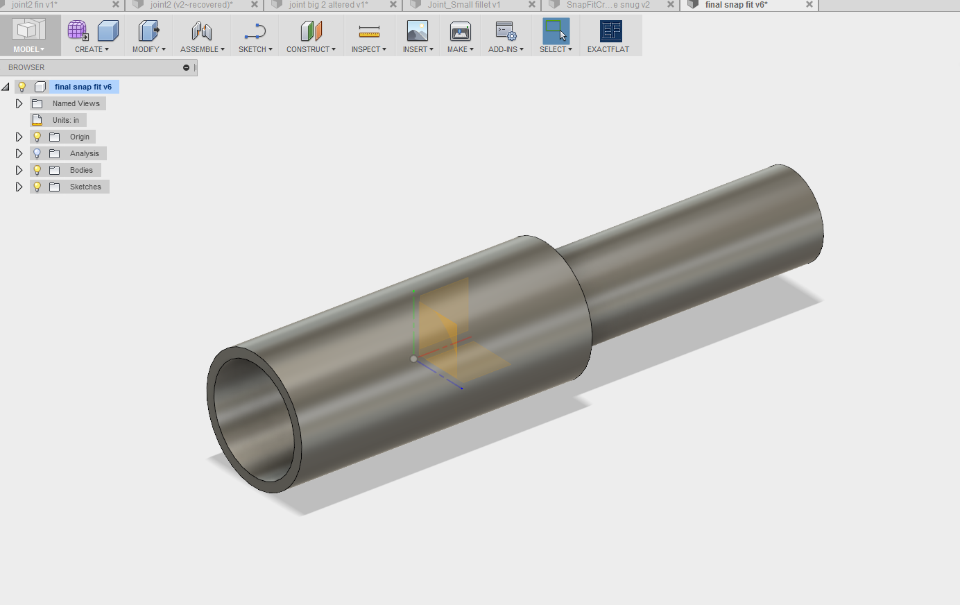
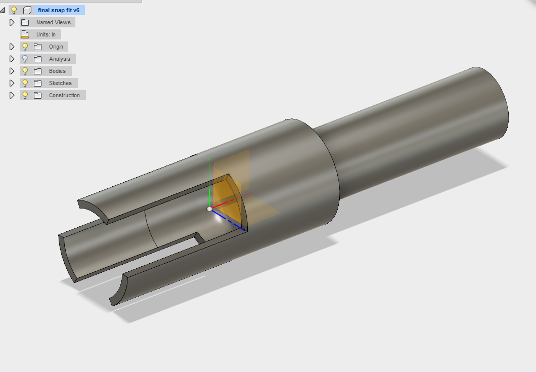
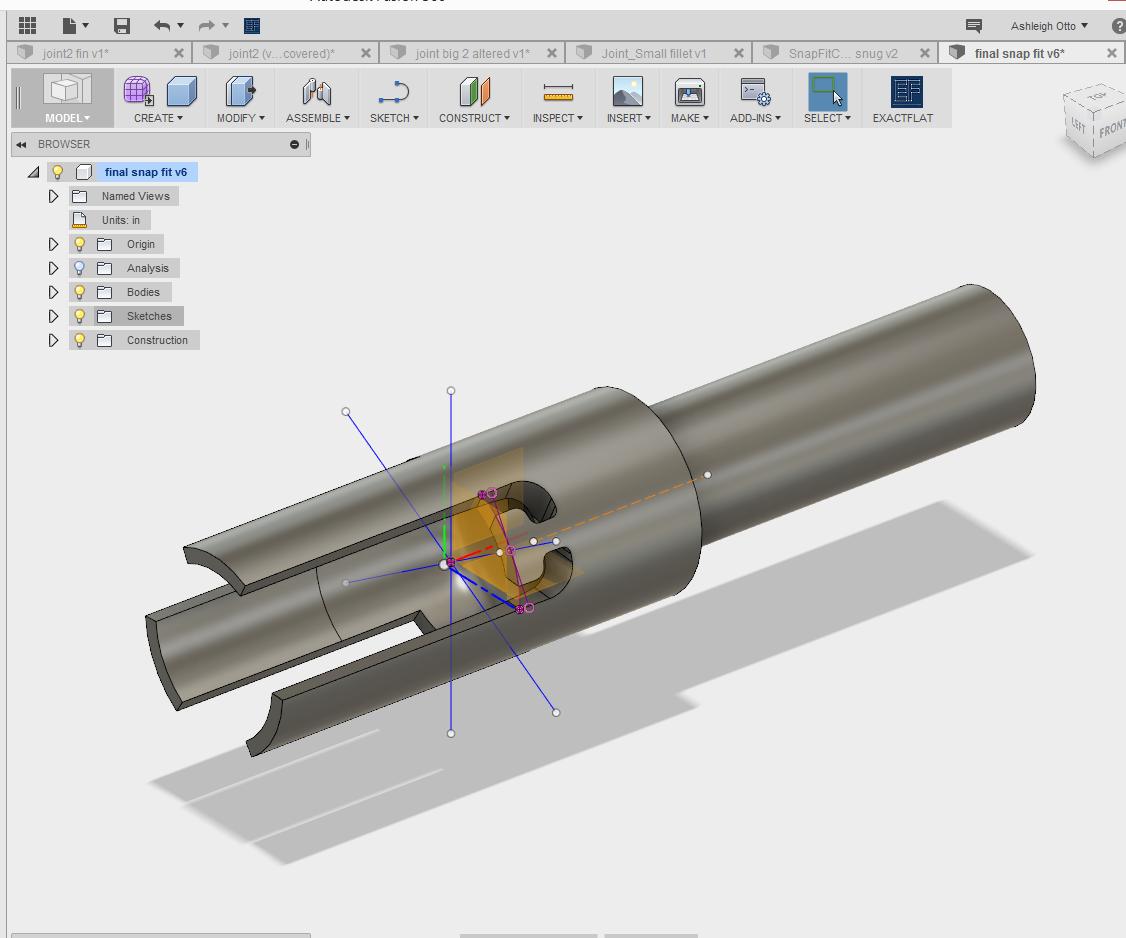
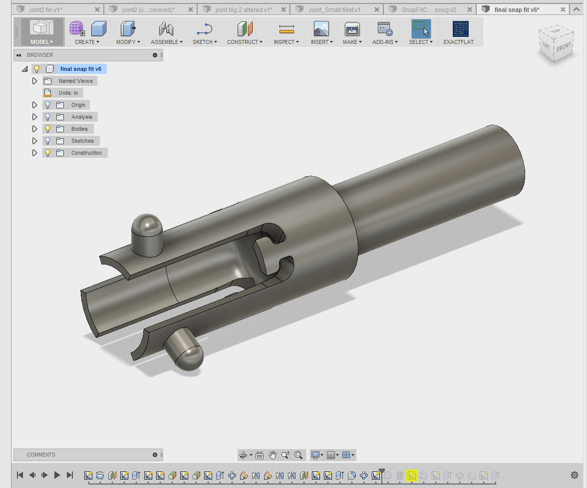
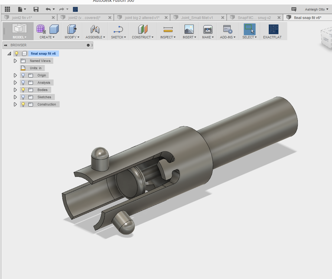
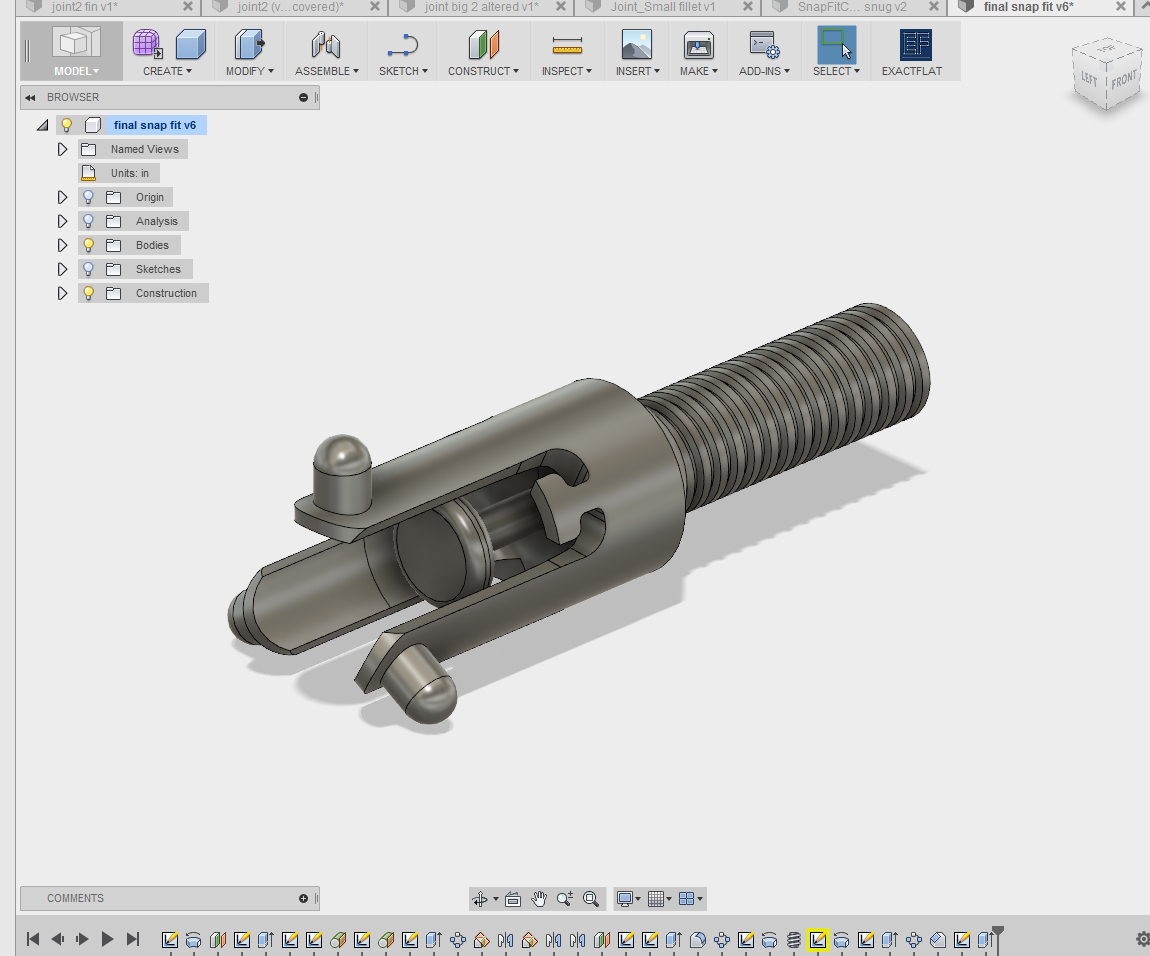
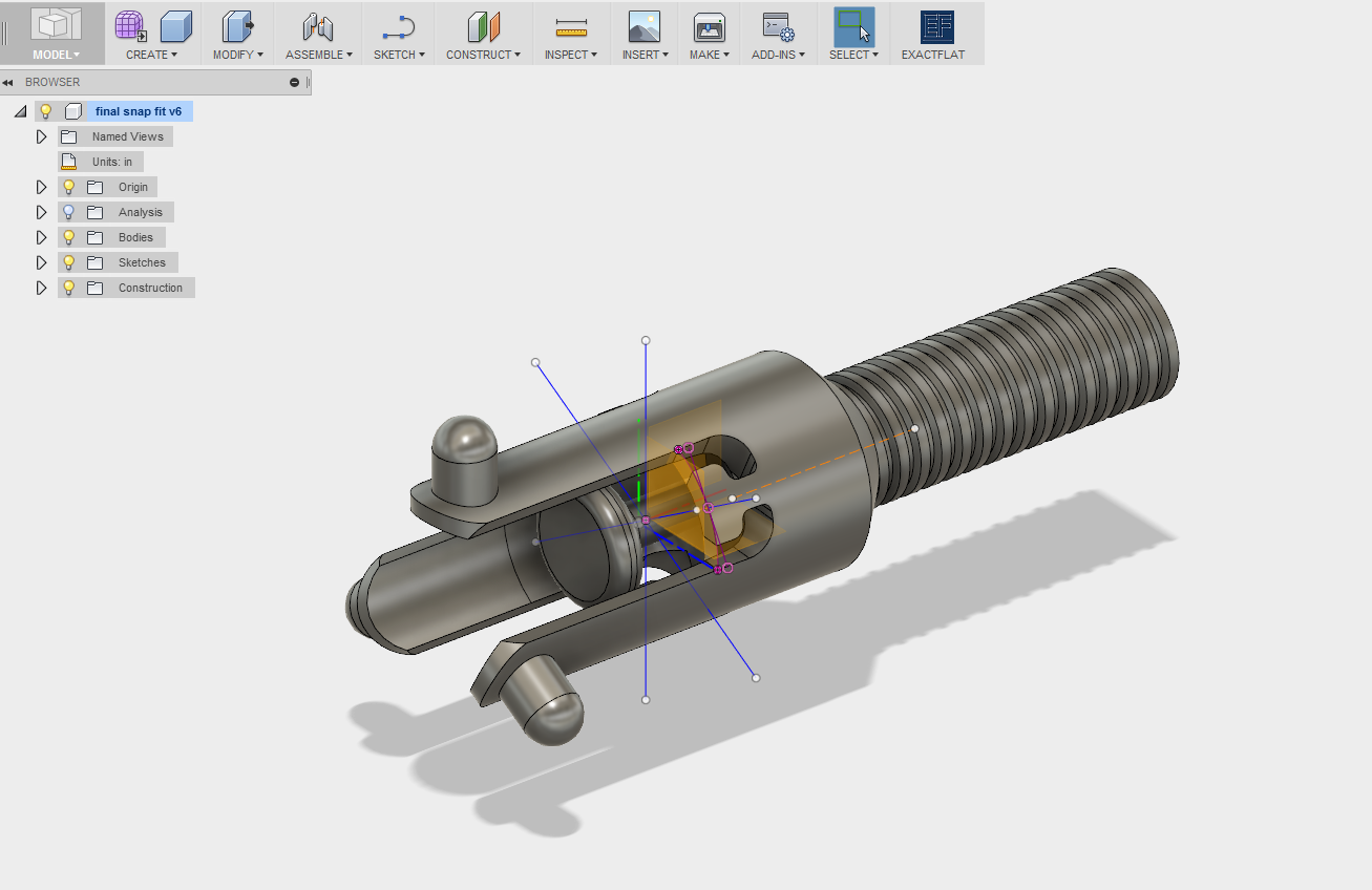
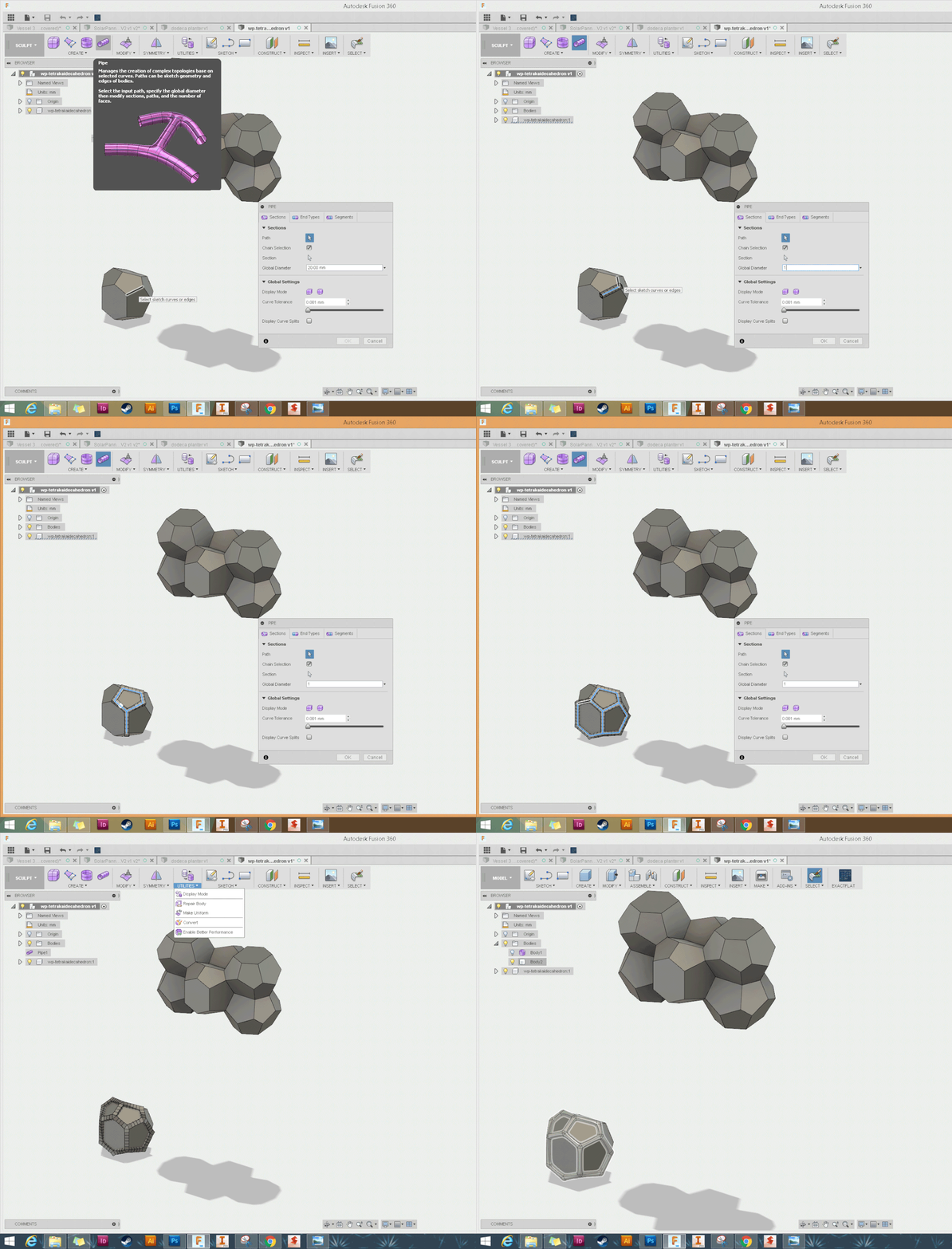
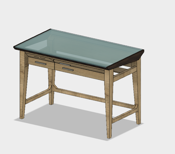
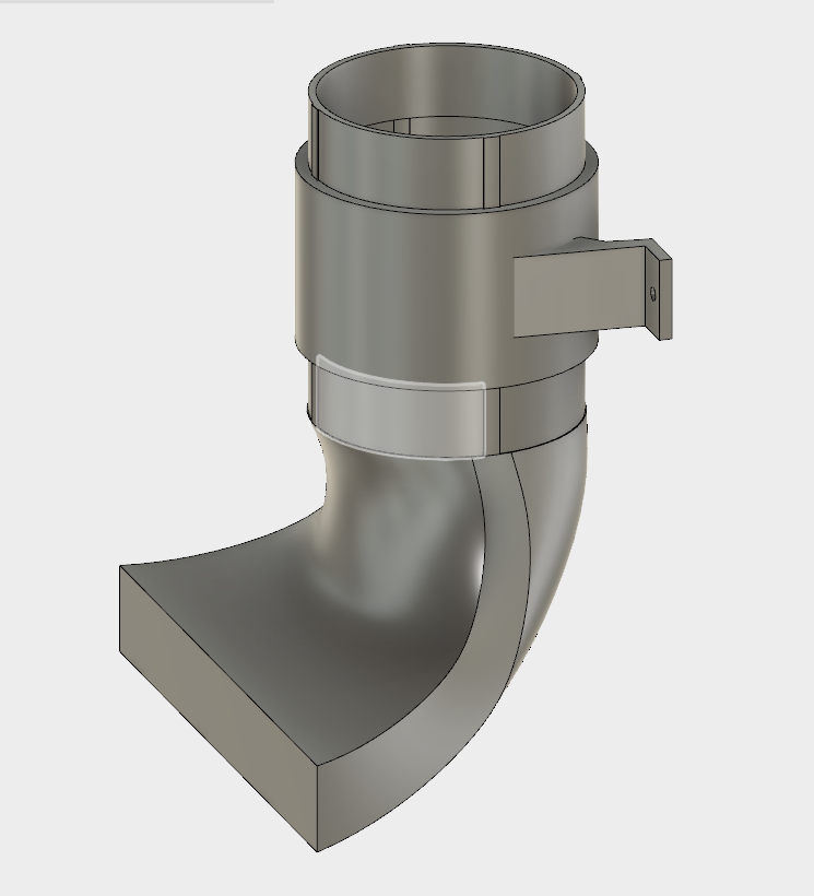
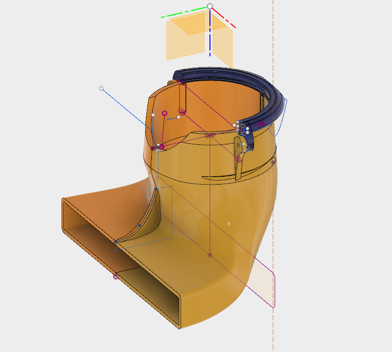
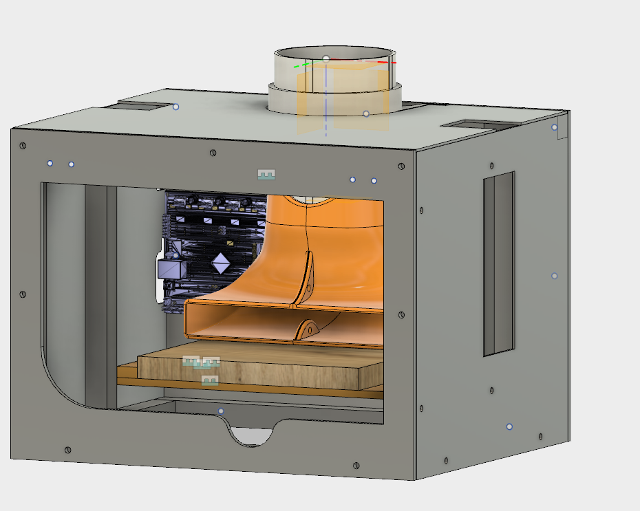
CAD is what brought me to Industrial Design. I took a dual enrollment CAD class in high school for college credit and was fortunate enough to learn from a man who was experienced and knowledgeable in drafting, ANSI/ISO standards, CAD software, 3D assemblies, and even floor plans. I took every class offered and learned how to create standard view, isometric, and orthographic drawings from scratch in basic AutoCAD using only lines, splines, arcs, and guides; appropriately constrained 3D assemblies with appropriate part and material schedules; basic Revit floor plans for construction documentation with appropriate details, wall widths, footers, etc; and even some 3D animation using Autodesk Maya and pen and paper storyboards.
I left high school with the determination to find a job that would allow me to do any part of the above for the rest of my life, and decided on Industrial design as it paired well with my interest in art and sculpture.
At Virginia Tech I learned Solidworks, Rhino, Fusion 360, Meshmixer, and was exposed to Grasshopper.
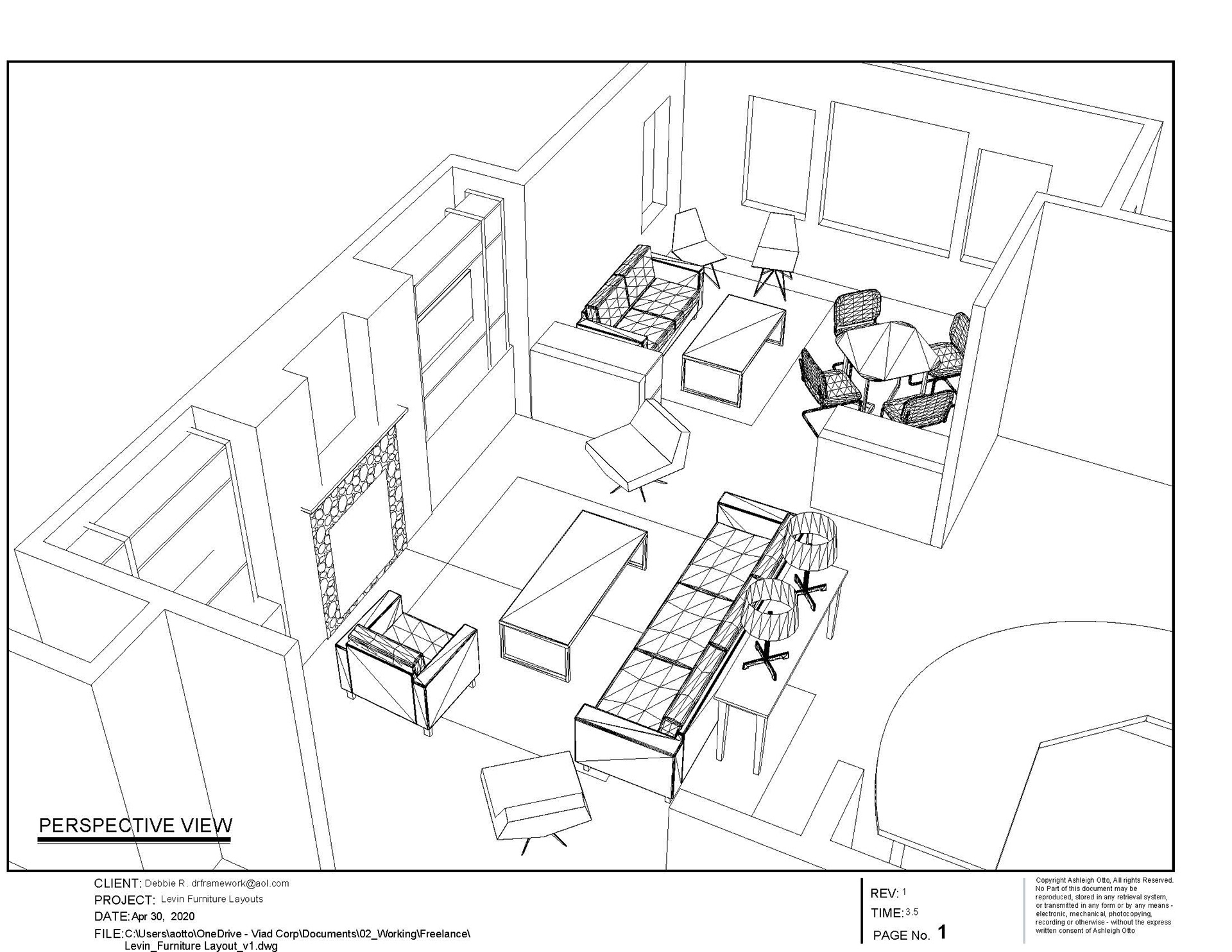
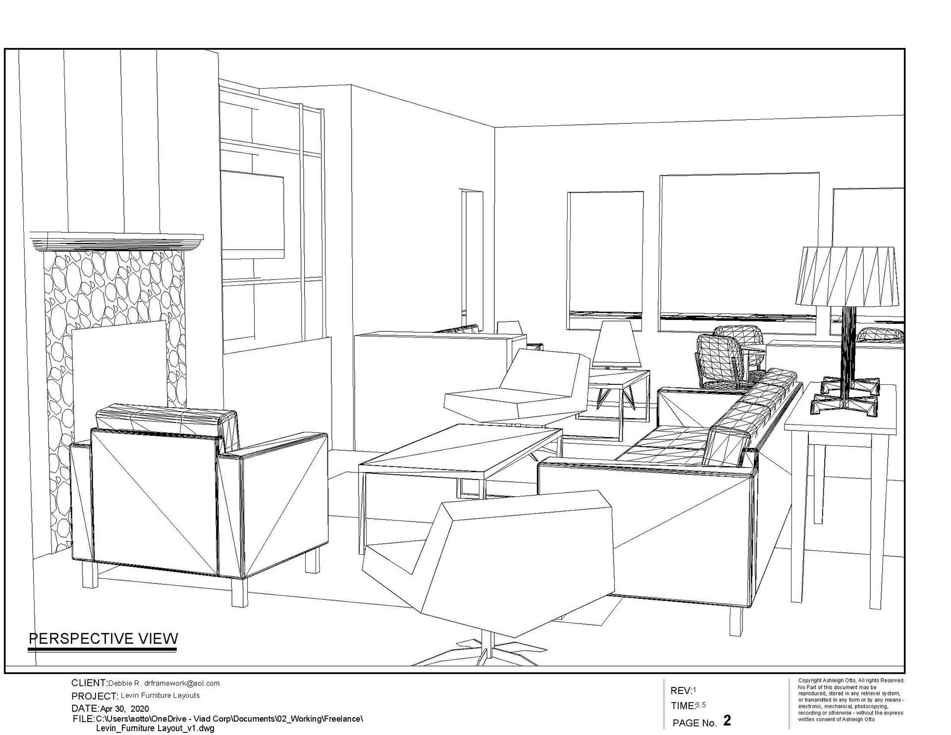
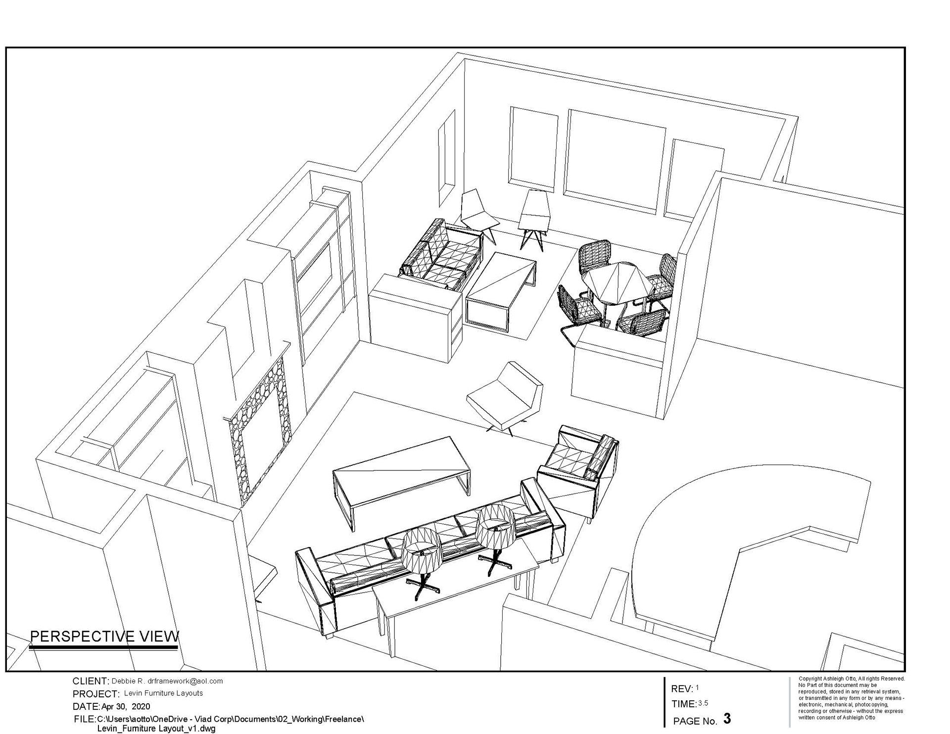
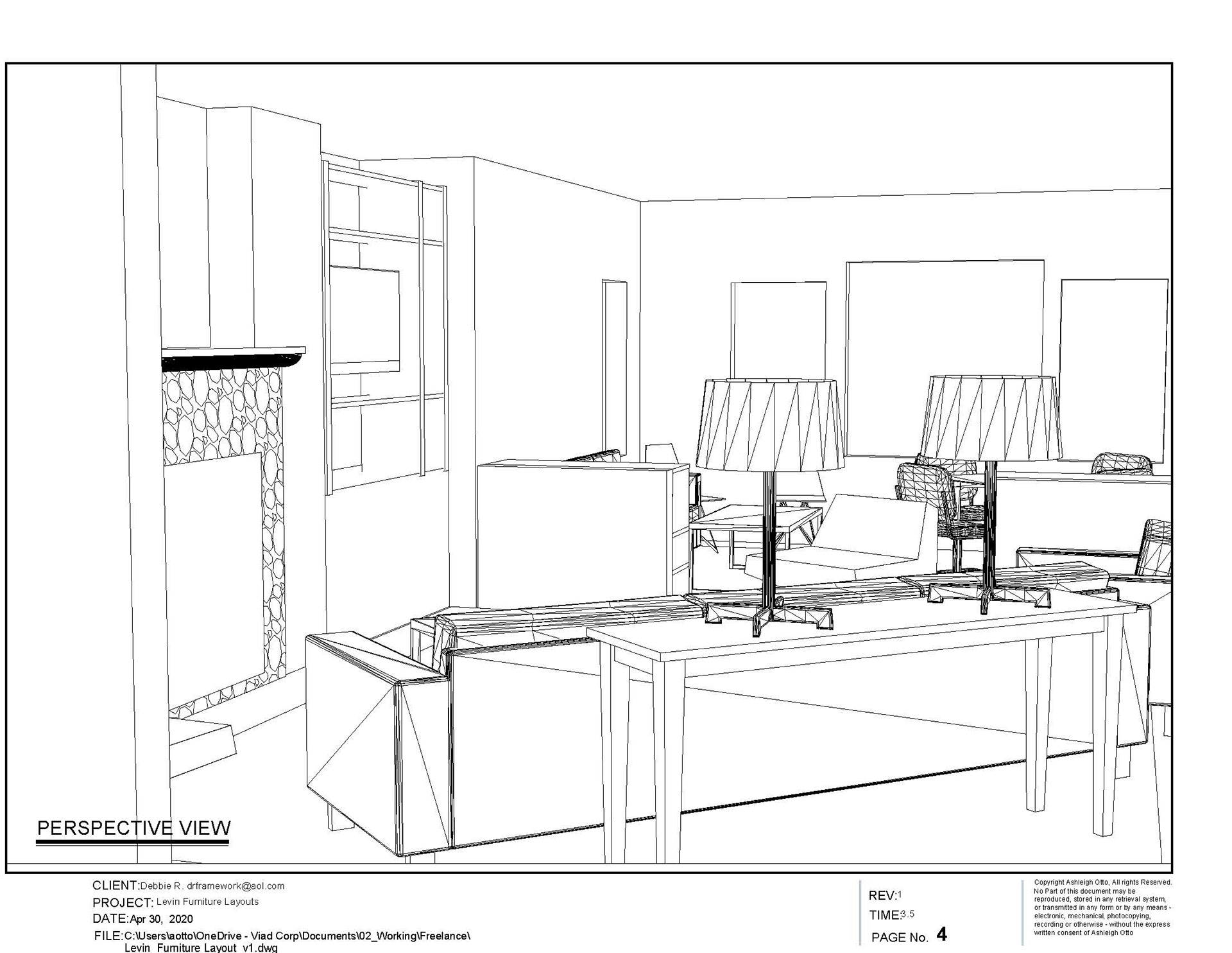
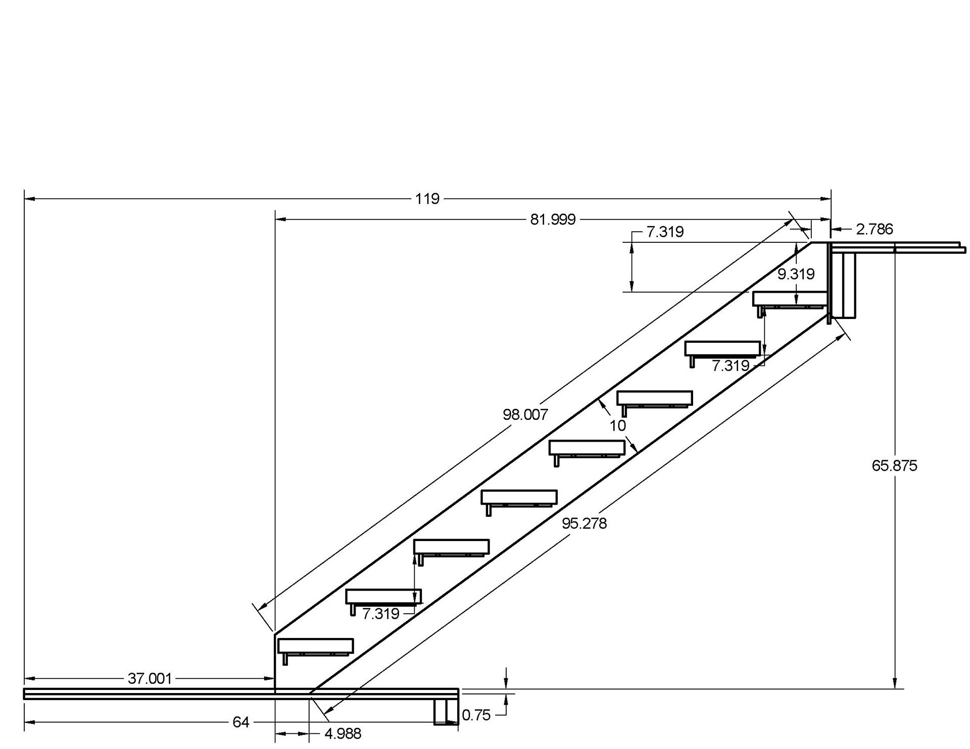
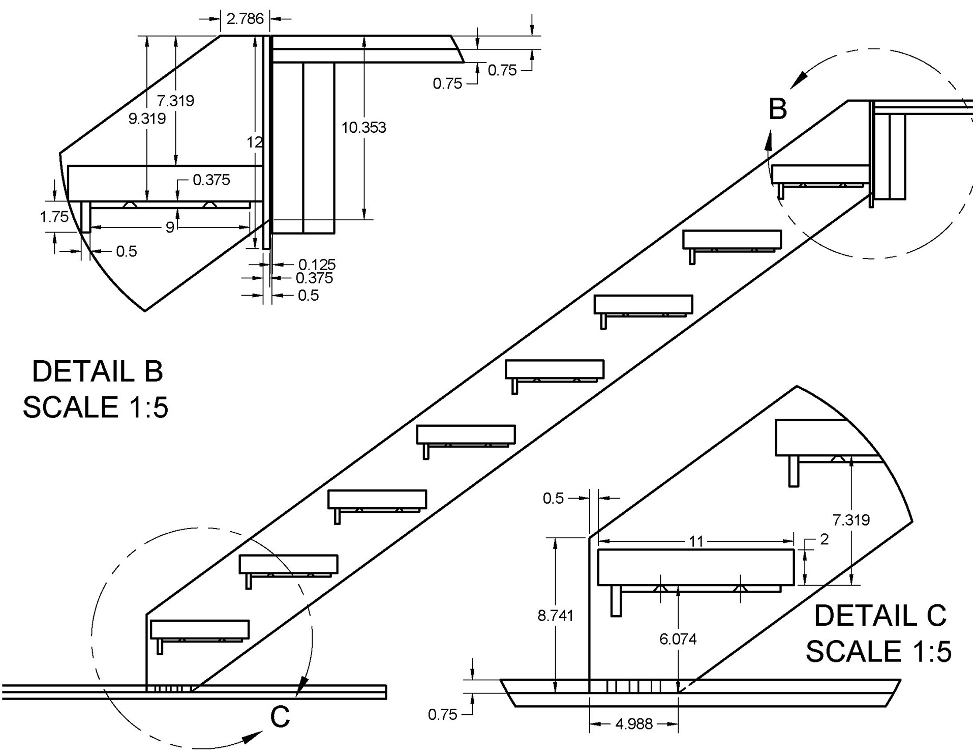
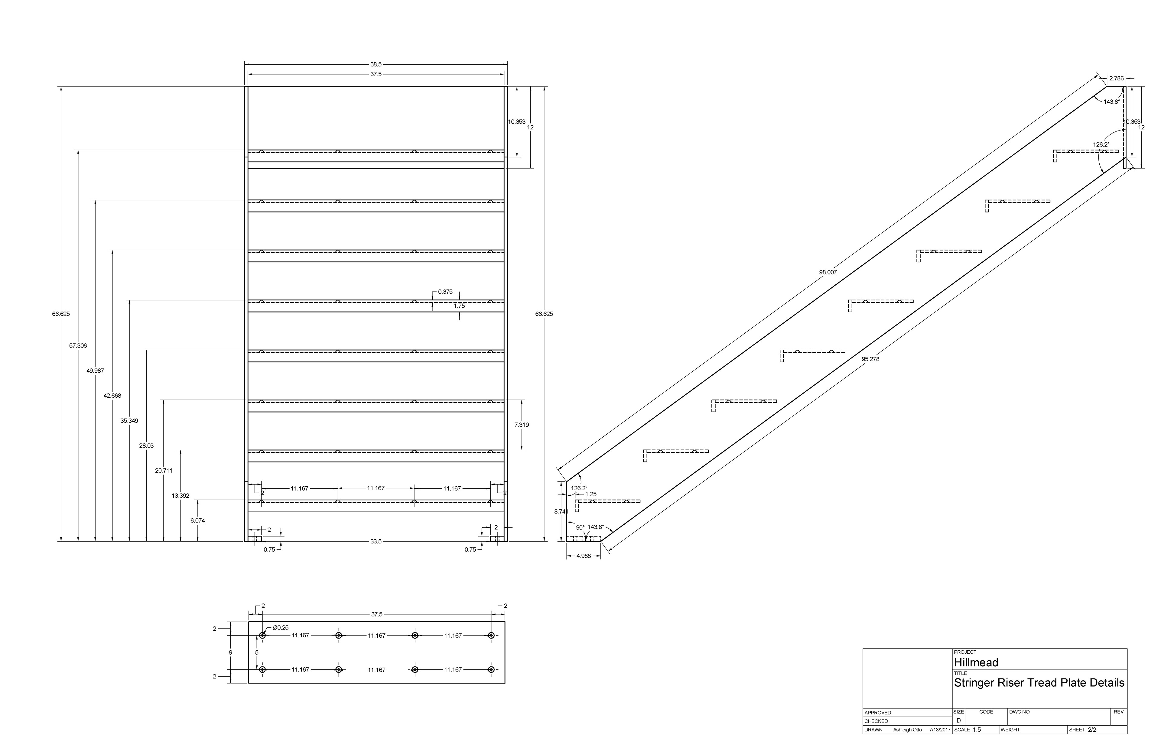
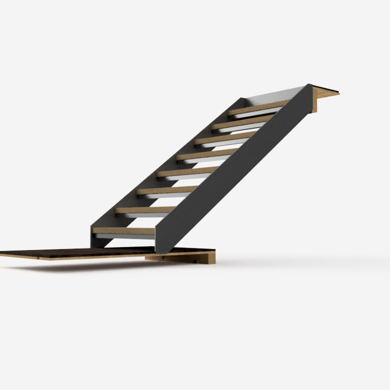
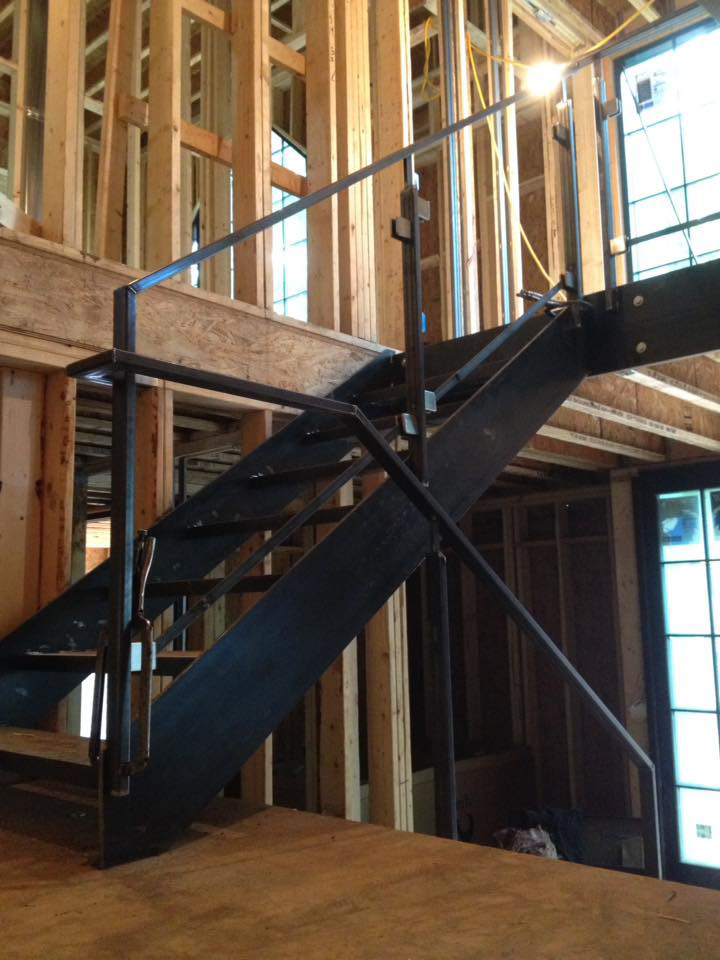
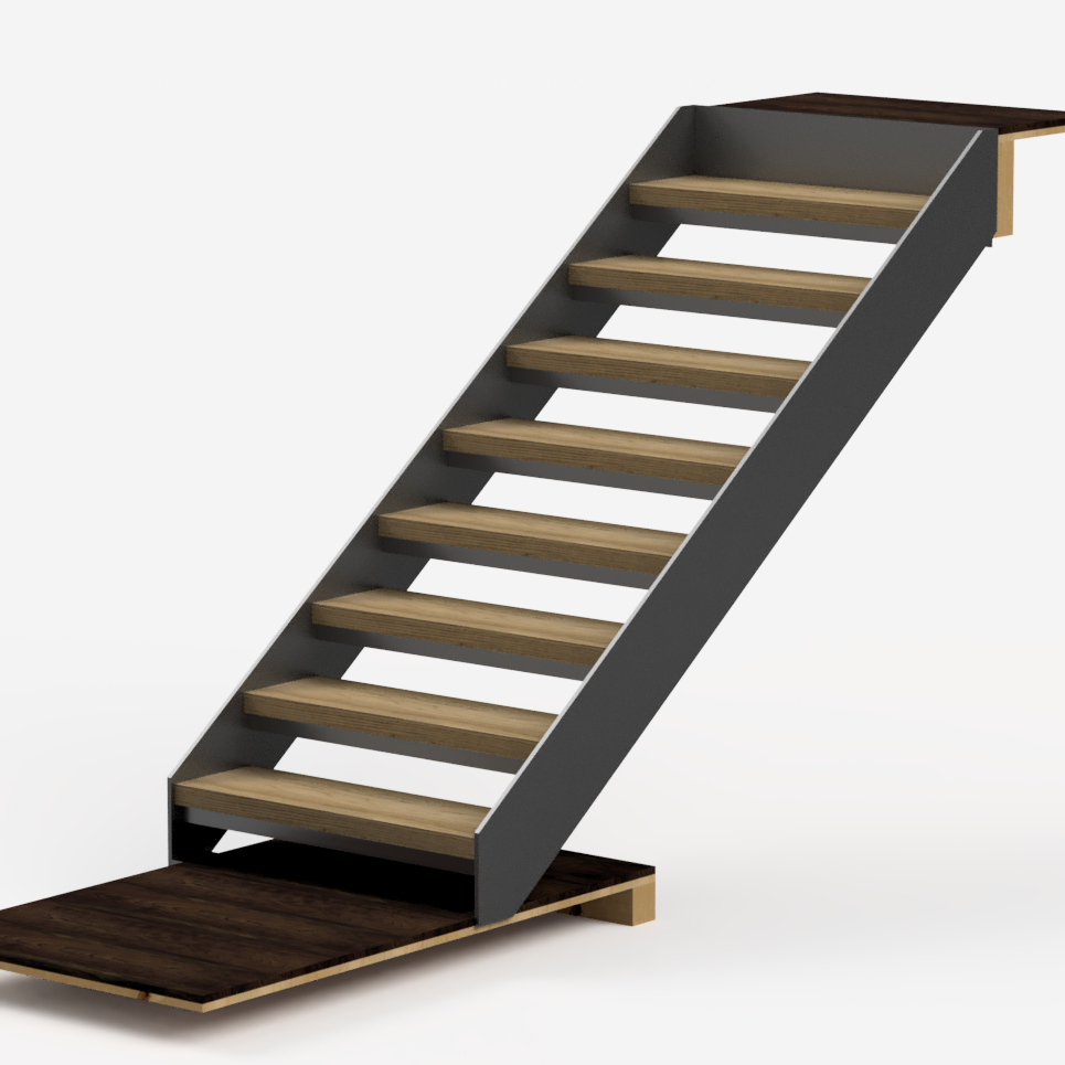
While job hunting, I monetized the CAD and Technical Drawing skills that I learned in high school and college by freelancing as a draftswoman. The drawings below are shop drawings I was contracted to do for a Design-Build steel fabricator.
My models and drawings were drawn from on site spec measurements. However, if you look closely, you will notice that for this project in particular the design for the bottom wood landing was altered after our initial spec to include an additional wood riser.
These drawings were used to secure the full deposit for this project for my client, and were used as the shop drawings -- or in this case the basis for shop drawings as the as-builts would differ by 1 riser.


For this project I was tasked to design a rolling cart that could ship and transport a set of 12 4x8 tableau boards and their corresponding structural aluminum legs. The trick was designing a solution that could feasibly fit through a 36" door. The dimensions of the parts themselves led to some technical design problem solving to make everything nest and fit together. Click the button above to see the model filled with legs and boards!

